ROS2 Jazzy 入門 (3) - LiDAR

「SDF」で作ったシンプルな差動二輪ロボットに「LiDAR」を追加して「rviz2」で視覚化します。
・Ubuntu 24.04
・ROS2 Jazzy
・Gazebo Harmonic
前回
1. SDF に障害物とLiDARを追加
前回の「SDF」に「障害物」と「LiDAR」を追加した「simple_robot_lidar.sdf」を作成します。
(1) SDFの編集。
・simple_robot_lidar.sdf
<?xml version="1.0" ?>
<!-- シンプルな差動二輪ロボットのSDFファイル -->
<sdf version="1.8">
<world name="simple_world">
<!-- 物理シミュレーションの設定 -->
<physics name="1ms" type="ignored">
<max_step_size>0.001</max_step_size> <!-- シミュレーションの時間刻み -->
<real_time_factor>1.0</real_time_factor> <!-- リアルタイム係数 -->
</physics>
<!-- 必要なプラグインの読み込み -->
<plugin filename="gz-sim-physics-system" name="gz::sim::systems::Physics"/>
<plugin filename="gz-sim-scene-broadcaster-system" name="gz::sim::systems::SceneBroadcaster"/>
<plugin filename="gz-sim-user-commands-system" name="gz::sim::systems::UserCommands"/>
<plugin filename="gz-sim-sensors-system" name="gz::sim::systems::Sensors"/>
<!-- 太陽光源の設定 -->
<light type="directional" name="sun">
<cast_shadows>true</cast_shadows>
<pose>0 0 10 0 0 0</pose> <!-- 光源の位置 -->
<diffuse>0.8 0.8 0.8 1</diffuse> <!-- 拡散光 -->
<specular>0.2 0.2 0.2 1</specular> <!-- 鏡面光 -->
<attenuation>
<range>1000</range>
<constant>0.9</constant>
<linear>0.01</linear>
<quadratic>0.001</quadratic>
</attenuation>
<direction>-0.5 0.1 -0.9</direction> <!-- 光の方向 -->
</light>
<!-- 地面モデルの設定 -->
<model name="ground_plane">
<static>true</static>
<link name="link">
<collision name="collision">
<geometry>
<plane>
<normal>0 0 1</normal>
</plane>
</geometry>
</collision>
<visual name="visual">
<geometry>
<plane>
<normal>0 0 1</normal>
<size>100 100</size> <!-- 地面の大きさ -->
</plane>
</geometry>
<material>
<ambient>0.8 0.8 0.8 1</ambient>
<diffuse>0.8 0.8 0.8 1</diffuse>
<specular>0.8 0.8 0.8 1</specular>
</material>
</visual>
</link>
</model>
<!-- 障害物1: 箱 -->
<model name="box1">
<static>true</static>
<pose>2 2 0.5 0 0 0</pose>
<link name="link">
<collision name="collision">
<geometry>
<box>
<size>1 1 1</size>
</box>
</geometry>
</collision>
<visual name="visual">
<geometry>
<box>
<size>1 1 1</size>
</box>
</geometry>
<material>
<ambient>1 0 0 1</ambient>
<diffuse>1 0 0 1</diffuse>
<specular>1 0 0 1</specular>
</material>
</visual>
</link>
</model>
<!-- 障害物2: 円柱 -->
<model name="cylinder1">
<static>true</static>
<pose>-2 -2 0.5 0 0 0</pose>
<link name="link">
<collision name="collision">
<geometry>
<cylinder>
<radius>0.5</radius>
<length>1.0</length>
</cylinder>
</geometry>
</collision>
<visual name="visual">
<geometry>
<cylinder>
<radius>0.5</radius>
<length>1.0</length>
</cylinder>
</geometry>
<material>
<ambient>0 1 0 1</ambient>
<diffuse>0 1 0 1</diffuse>
<specular>0 1 0 1</specular>
</material>
</visual>
</link>
</model>
<!-- 北側の壁 -->
<model name="north_wall">
<static>true</static>
<pose>0 5 1 0 0 0</pose>
<link name="link">
<collision name="collision">
<geometry>
<box>
<size>10 0.2 2</size>
</box>
</geometry>
</collision>
<visual name="visual">
<geometry>
<box>
<size>10 0.2 2</size>
</box>
</geometry>
<material>
<ambient>0.7 0.7 0.7 1</ambient>
<diffuse>0.7 0.7 0.7 1</diffuse>
<specular>0.7 0.7 0.7 1</specular>
</material>
</visual>
</link>
</model>
<!-- 南側の壁 -->
<model name="south_wall">
<static>true</static>
<pose>0 -5 1 0 0 0</pose>
<link name="link">
<collision name="collision">
<geometry>
<box>
<size>10 0.2 2</size>
</box>
</geometry>
</collision>
<visual name="visual">
<geometry>
<box>
<size>10 0.2 2</size>
</box>
</geometry>
<material>
<ambient>0.7 0.7 0.7 1</ambient>
<diffuse>0.7 0.7 0.7 1</diffuse>
<specular>0.7 0.7 0.7 1</specular>
</material>
</visual>
</link>
</model>
<!-- 東側の壁 -->
<model name="east_wall">
<static>true</static>
<pose>5 0 1 0 0 1.5708</pose>
<link name="link">
<collision name="collision">
<geometry>
<box>
<size>10 0.2 2</size>
</box>
</geometry>
</collision>
<visual name="visual">
<geometry>
<box>
<size>10 0.2 2</size>
</box>
</geometry>
<material>
<ambient>0.7 0.7 0.7 1</ambient>
<diffuse>0.7 0.7 0.7 1</diffuse>
<specular>0.7 0.7 0.7 1</specular>
</material>
</visual>
</link>
</model>
<!-- 西側の壁 -->
<model name="west_wall">
<static>true</static>
<pose>-5 0 1 0 0 1.5708</pose>
<link name="link">
<collision name="collision">
<geometry>
<box>
<size>10 0.2 2</size>
</box>
</geometry>
</collision>
<visual name="visual">
<geometry>
<box>
<size>10 0.2 2</size>
</box>
</geometry>
<material>
<ambient>0.7 0.7 0.7 1</ambient>
<diffuse>0.7 0.7 0.7 1</diffuse>
<specular>0.7 0.7 0.7 1</specular>
</material>
</visual>
</link>
</model>
<!-- ロボット本体の設定 -->
<model name="simple_robot">
<pose>0 0 0.1 0 0 0</pose> <!-- ロボットの初期位置 -->
<!-- ベースリンク(本体) -->
<link name="base_link">
<inertial>
<mass>1.0</mass> <!-- 本体の質量 -->
<inertia> <!-- 慣性モーメント -->
<ixx>0.0835</ixx>
<ixy>0</ixy>
<ixz>0</ixz>
<iyy>0.1209</iyy>
<iyz>0</iyz>
<izz>0.1209</izz>
</inertia>
</inertial>
<visual name="visual">
<geometry>
<box>
<size>0.5 0.3 0.1</size> <!-- 本体のサイズ -->
</box>
</geometry>
<material>
<ambient>0 0 1 1</ambient> <!-- 青色 -->
<diffuse>0 0 1 1</diffuse>
<specular>0 0 1 1</specular>
</material>
</visual>
<collision name="collision">
<geometry>
<box>
<size>0.5 0.3 0.1</size>
</box>
</geometry>
</collision>
<!-- LiDAR -->
<sensor name="lidar" type="gpu_lidar">
<pose>0.2 0 0.15 0 0 0</pose>
<topic>lidar</topic>
<update_rate>10</update_rate>
<lidar>
<scan>
<horizontal>
<samples>360</samples>
<resolution>1</resolution>
<min_angle>-3.14159</min_angle>
<max_angle>3.14159</max_angle>
</horizontal>
</scan>
<range>
<min>0.1</min>
<max>10.0</max>
<resolution>0.01</resolution>
</range>
<noise>
<type>gaussian</type>
<mean>0.0</mean>
<stddev>0.01</stddev>
</noise>
</lidar>
<visualize>true</visualize>
<always_on>1</always_on>
</sensor>
</link>
<!-- 左車輪 -->
<link name="left_wheel">
<pose relative_to="base_link">0 0.175 0 -1.5708 0 0</pose> <!-- 左車輪の位置 -->
<inertial>
<mass>0.5</mass> <!-- 車輪の質量 -->
<inertia>
<ixx>0.00125</ixx>
<ixy>0</ixy>
<ixz>0</ixz>
<iyy>0.00125</iyy>
<iyz>0</iyz>
<izz>0.002</izz>
</inertia>
</inertial>
<visual name="visual">
<geometry>
<cylinder>
<radius>0.1</radius> <!-- 車輪の半径 -->
<length>0.05</length> <!-- 車輪の幅 -->
</cylinder>
</geometry>
<material>
<ambient>0 0 0 1</ambient> <!-- 黒色 -->
<diffuse>0 0 0 1</diffuse>
<specular>0 0 0 1</specular>
</material>
</visual>
<collision name="collision">
<geometry>
<cylinder>
<radius>0.1</radius>
<length>0.05</length>
</cylinder>
</geometry>
</collision>
</link>
<!-- 右車輪(左車輪と同様の設定) -->
<link name="right_wheel">
<pose relative_to="base_link">0 -0.175 0 -1.5708 0 0</pose> <!-- 右車輪の位置 -->
<inertial>
<mass>0.5</mass>
<inertia>
<ixx>0.00125</ixx>
<ixy>0</ixy>
<ixz>0</ixz>
<iyy>0.00125</iyy>
<iyz>0</iyz>
<izz>0.002</izz>
</inertia>
</inertial>
<visual name="visual">
<geometry>
<cylinder>
<radius>0.1</radius>
<length>0.05</length>
</cylinder>
</geometry>
<material>
<ambient>0 0 0 1</ambient>
<diffuse>0 0 0 1</diffuse>
<specular>0 0 0 1</specular>
</material>
</visual>
<collision name="collision">
<geometry>
<cylinder>
<radius>0.1</radius>
<length>0.05</length>
</cylinder>
</geometry>
</collision>
</link>
<!-- キャスター(補助輪) -->
<link name="caster">
<pose relative_to="base_link">-0.2 0 -0.05 0 0 0</pose> <!-- キャスターの位置 -->
<inertial>
<mass>0.1</mass> <!-- キャスターの質量 -->
<inertia>
<ixx>0.0001</ixx>
<ixy>0</ixy>
<ixz>0</ixz>
<iyy>0.0001</iyy>
<iyz>0</iyz>
<izz>0.0001</izz>
</inertia>
</inertial>
<collision name="collision">
<geometry>
<sphere>
<radius>0.05</radius> <!-- キャスターの半径 -->
</sphere>
</geometry>
</collision>
<visual name="visual">
<geometry>
<sphere>
<radius>0.05</radius>
</sphere>
</geometry>
<material>
<ambient>0.8 0.8 0.8 1</ambient> <!-- グレー色 -->
<diffuse>0.8 0.8 0.8 1</diffuse>
<specular>0.8 0.8 0.8 1</specular>
</material>
</visual>
</link>
<!-- 左車輪のジョイント -->
<joint name="left_wheel_joint" type="revolute">
<parent>base_link</parent>
<child>left_wheel</child>
<axis>
<xyz>0 0 1</xyz> <!-- 回転軸 -->
<limit>
<lower>-1.79769e+308</lower> <!-- 回転制限なし -->
<upper>1.79769e+308</upper>
</limit>
</axis>
</joint>
<!-- 右車輪のジョイント -->
<joint name="right_wheel_joint" type="revolute">
<parent>base_link</parent>
<child>right_wheel</child>
<axis>
<xyz>0 0 1</xyz>
<limit>
<lower>-1.79769e+308</lower>
<upper>1.79769e+308</upper>
</limit>
</axis>
</joint>
<!-- キャスターのジョイント(固定) -->
<joint name="caster_joint" type="fixed">
<parent>base_link</parent>
<child>caster</child>
</joint>
<!-- 差動駆動システムのプラグイン -->
<plugin filename="gz-sim-diff-drive-system" name="gz::sim::systems::DiffDrive">
<topic>cmd_vel</topic> <!-- 速度指令のトピック名 -->
<left_joint>left_wheel_joint</left_joint> <!-- 左車輪のジョイント名 -->
<right_joint>right_wheel_joint</right_joint> <!-- 右車輪のジョイント名 -->
<wheel_separation>0.35</wheel_separation> <!-- 車輪間距離 -->
<wheel_radius>0.1</wheel_radius> <!-- 車輪半径 -->
<odom_publish_frequency>50</odom_publish_frequency> <!-- Odometry公開の頻度 -->
</plugin>
</model>
</world>
</sdf>・gz::sim::systems::Sensors : センサーデータのシミュレーション (カメラ、LiDAR、IMUなど)
2. Gazebo の起動
(1) ターミナルを開いて「Gazebo」を起動。
障害物が追加されています。
$ gz sim simple_robot_lidar.sdf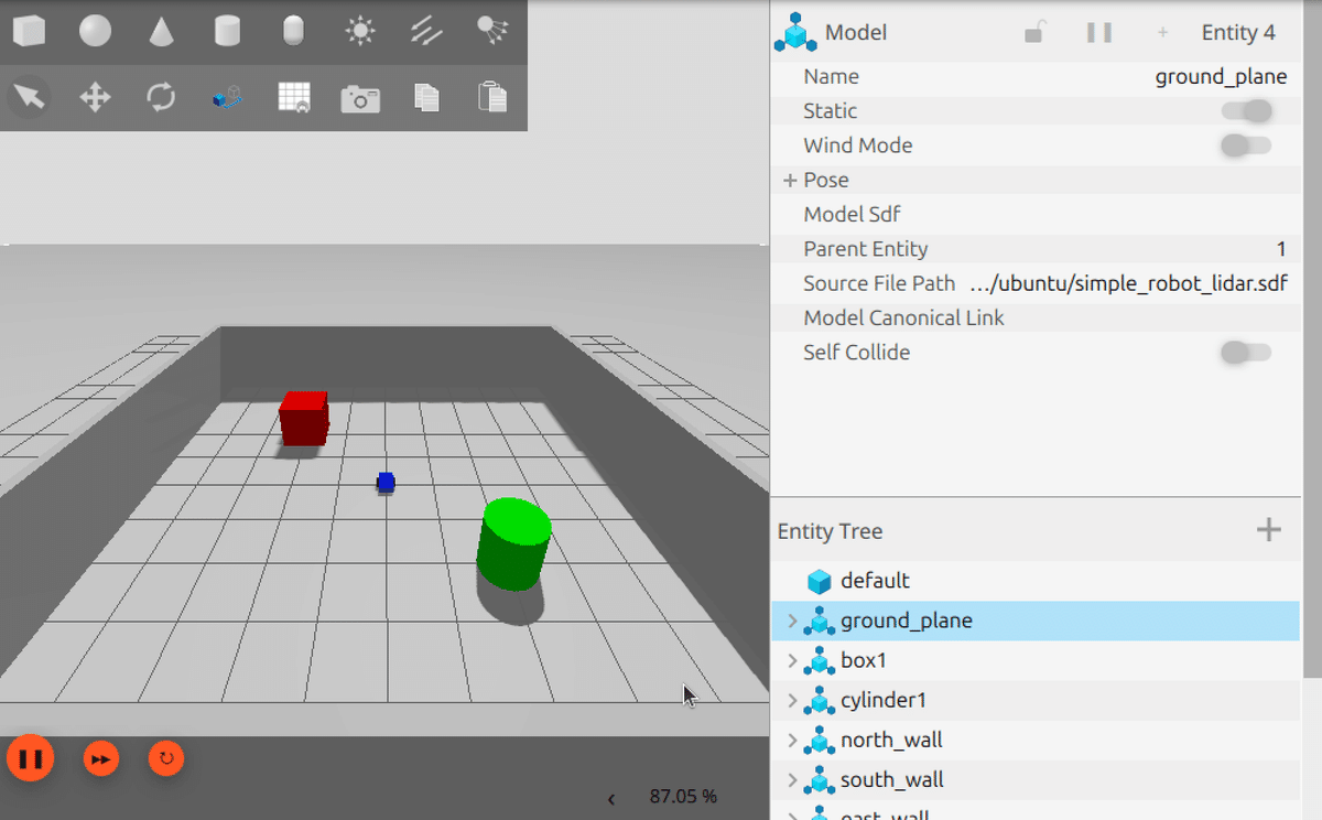
(2) 別のターミナルを開いて「/cmd_vel」と「/lidar」をROS2にブリッジ。
$ ros2 run ros_gz_bridge parameter_bridge /cmd_vel@geometry_msgs/msg/Twist@gz.msgs.Twist
$ ros2 run ros_gz_bridge parameter_bridge /lidar@sensor_msgs/msg/LaserScan@gz.msgs.LaserScan
(3) 別のターミナルを開いて「teleop_twist_keyboard」を起動。
$ ros2 run teleop_twist_keyboard teleop_twist_keyboard(4) 「Gazebo」左下の▶をクリック。
物理シミュレーションが開始します。
(5) 「teleop_twist_keyboard」のターミナルをフォーカスして、「i」をクリック。
ロボットが前進します。
3. LiDAR の動作確認
(1) 「/cmd_vel」と「/lidar」がトピックに追加されていることを確認。
ros2 topic list/cmd_vel
/lidar
/parameter_events
/rosout(2) 「/lidar」のデータ型を確認。
$ ros2 topic info /lidarType: sensor_msgs/msg/LaserScan
Publisher count: 1
Subscription count: 1(3)「/lidar」のリアルタイムデータを確認。
$ ros2 topic echo /lidarheader:
stamp:
sec: 10
nanosec: 700000000
frame_id: simple_robot/base_link/lidar
angle_min: -3.141590118408203
angle_max: 3.141590118408203
angle_increment: 0.017501894384622574
time_increment: 0.0
scan_time: 0.0
range_min: 0.10000000149011612
range_max: 10.0
ranges:
- .inf
:
- .inf
- 2.817147731781006
- 2.69244647026062
- 2.639533758163452
- 2.5821311473846436
- 2.5302374362945557
- 2.5058858394622803
- 2.493062973022461
- 2.4816648960113525
- 2.491161584854126
- 2.4732019901275635
- 2.4713101387023926
- 2.4868974685668945
- 2.497936964035034
- 2.524531841278076
- 2.530487060546875
- 2.5578346252441406
- 2.589235782623291
- 2.6764042377471924
- 2.763381242752075
- .inf
:
- .inf
- '...'
intensities:
- 0.0
:
- 0.0
- '...'sensor_msgs/LaserScan のデータ型は次のとおりです。
・sensor_msgs/LaserScan
・float32 angle_max : スキャンの終了角度 (ラジアン)
・float32 angle_increment : 各スキャン点の角度 (ラジアン)
・float32 time_increment : 各スキャン点を取得する間の時間 (秒)
・float32 scan_time : 1つのスキャン全体にかかった時間 (秒)
・float32 range_min : 有効な範囲の最小値 (メートル)
・float32 range_max : 有効な範囲の最大値 (メートル)
・float32[] ranges : スキャンで取得された距離データの配列(メートル)。
・float32[] intensities : スキャンで取得された強度データの配列 (オプション)
4. rviz2 での視覚化
「rviz2」は、ROS2の視覚化ツールです。主にロボットの動作、センサーのデータ、経路計画、環境マップなどをリアルタイムで視覚化します。
(1) rviz2 の起動。
$ rviz2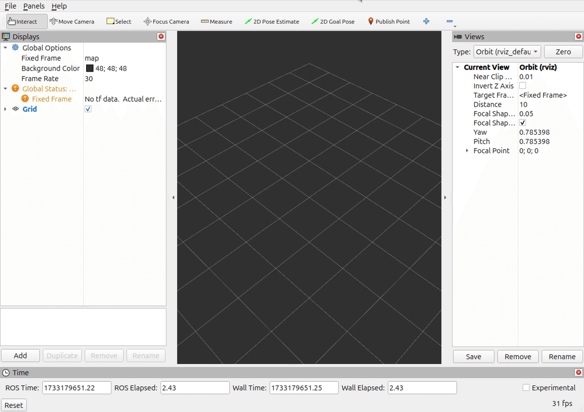
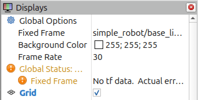
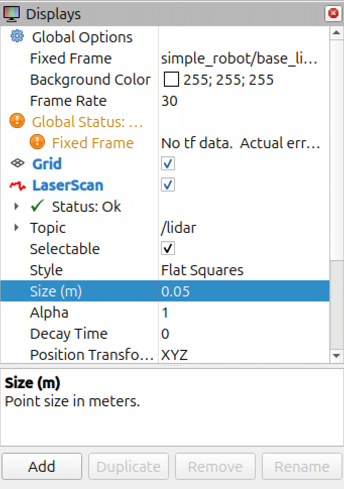
(2) 左側の設定項目を以下のように設定。
・Fixed Frame : simple_robot/base_link/lidar
「ros2 topic echo /lidar」の「frame_id」を指定します。
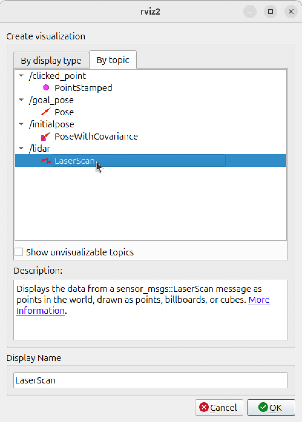
(2) 左下の「Add」をクリックし、「By topic → /lidar → LaserScan」を選択し、「OK」をクリック。
・Topic : /lidar
トピック名を指定します。
・Size (m) : 0.05
見やすさのため指定しました。
(3) 「rviz2」のメニュー「File → Save Config」で設定を保存。
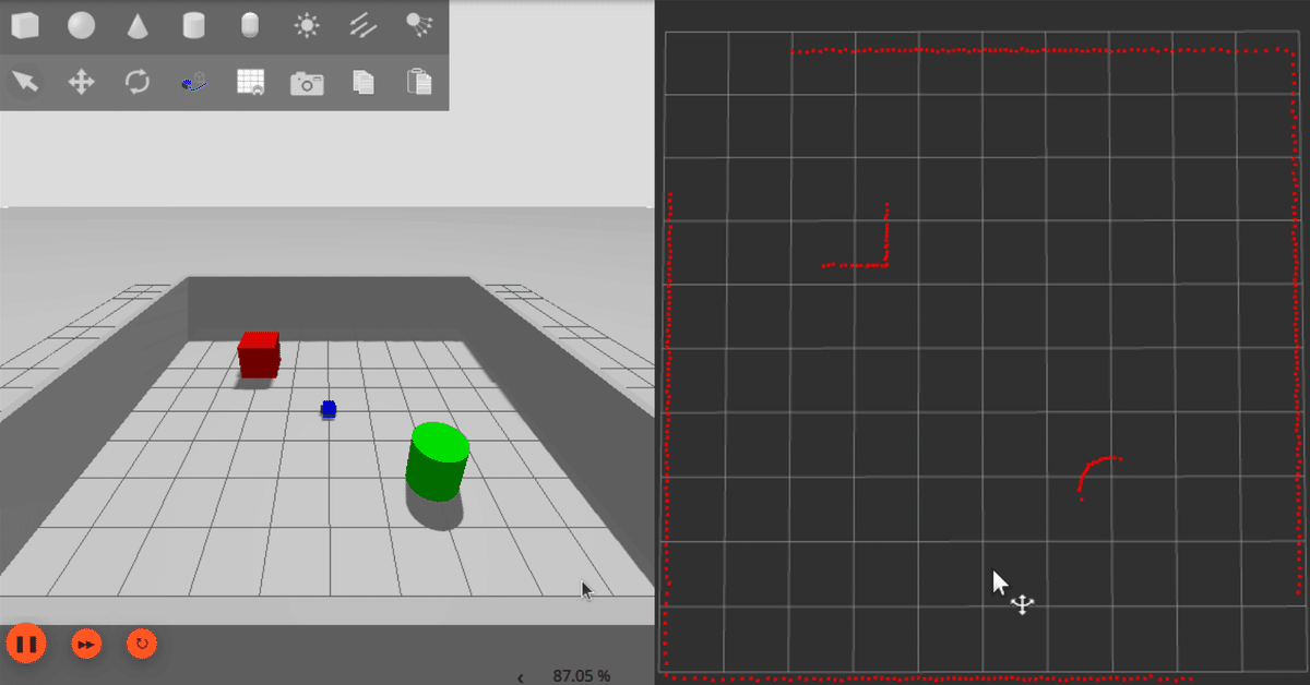
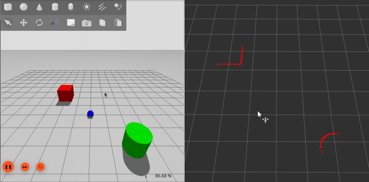
(4) 視覚化を確認。
ロボットを操作して、LiDARが障害物をどのように認識しているかを確認します。
3. launchファイル
(1) launchファイルの作成。
・run_simple_robot_lidar.py
from launch import LaunchDescription
from launch.actions import ExecuteProcess

def generate_launch_description():
    return LaunchDescription([
        # Gazeboの起動
        ExecuteProcess(
            cmd=['gz', 'sim', 'simple_robot_lidar.sdf'],
            output='log',
            log_cmd=True
        ),

        # rviz2の起動
        ExecuteProcess(
            cmd=['rviz2'],
            output='log',
            log_cmd=True
        ),

        # ブリッジの起動
        ExecuteProcess(
            cmd=[
                'ros2', 'run', 'ros_gz_bridge', 'parameter_bridge',
                '/cmd_vel@geometry_msgs/msg/Twist@gz.msgs.Twist'
            ],
            output='log',
            log_cmd=True
        ),
        ExecuteProcess(
            cmd=[
                'ros2', 'run', 'ros_gz_bridge', 'parameter_bridge',
                '/lidar@sensor_msgs/msg/LaserScan@gz.msgs.LaserScan'
            ],
            output='log',
            log_cmd=True
        ),

        # teleop_twist_keyboardの起動
        ExecuteProcess(
            cmd=['ros2', 'run', 'teleop_twist_keyboard', 'teleop_twist_keyboard'],
            output='screen',
            prefix='xterm -e'
        ),
    ])
(2) launchファイルの実行。
$ ros2 launch ~/run_simple_robot_lidar.py