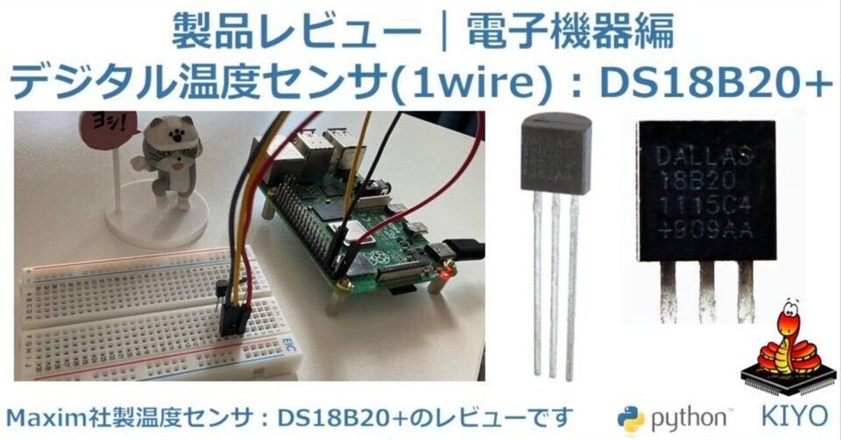
製品レビュー|電子機器14:温度センサ-1Wire(DS18B20+)

1.概要
購入した製品の使い方および感想用記事です。
今回は「デジタル温度センサ(1wire)DS18B20+(860円/個(税込))」をレビューしました。

1-1.基本仕様
Maxim社の1wireインターフェースのシンプルなデジタル温度センサーです。データ線から電源を供給可能ですべてのデバイスに対してユニークな64ビットのシリアルコードを付与(内部ROMに書込済)してあります。
※型番の「+」は鉛フリー品(lead free)という意味です。
https://www.analog.com/jp/products/ds18b20.html
【コラム:Analog Devices社のMaxim社買収】
Analog Devices社(ADI)は2021年8月26日にMaxim Integrated Productsの買収を完了しており、現在はADIの子会社である。
1-1-1.仕様の概要
基本の概要は下記参照。
電源電圧:3~5.5V
測定温度範囲:ー55~125℃
分解能:9bit~12bitで選択可能(デフォルト:12bit)
それぞれ0.5℃、0.25℃、0.125℃、0.0625℃
測定精度:±0.5℃@ー10~85℃
出力(インターフェース):1-Wire

1-1-2.ブロック図
下図の通り。
追加電源を使用しない代わりに、信号線DQにはプルアップ抵抗が必要

1-2.詳細仕様
1-2-1.ピン配置
下図の通り


2.製品原理
製品の動作原理に関する部分を説明します。
2-1.1-wireとは
1-Wire はマキシム・インテグレーテッド社(現在はアナログ・デバイセズ社の子会社)が登録商標しているシリアル通信規格です。
接地線(GND)と一本の信号線(兼電力供給線)だけで低速なデータ転送を行い、送受信回路を絶縁対応することも可能です。

他のシリアル通信規格(SPI, I2Cなど)と比較して、1-Wireは1線式の通信インターフェースであり、GNDと、1本の通信線 (DQ) でマスターとスレーブが接続されます。

2-2.バンドギャップベースデジタル温度センサ
温度センサーは下図のように複数種類の製品があります。


デジタル温度センサ(1wire)DS18B20+の測定原理が見当たらなかったのですが、データシートに「バンドギャップベースデジタル温度センサー」とありました。この中にも測定原理まで書いていないため、現状では不明です。

出典:バンドギャップベースデジタル温度センサー誤差の曲線近似(カーブフィッティング)
【参考:過去記事の温度センサ一覧】
過去記事で紹介した温度センサは下記の通り。
3.部材購入
3-1.購入品
部品は本体のみ購入しました。
3-2.準備必須品
その他必需品は下記の通りです。
抵抗器はプルアップ用のため代用できるものがあれば、それでも良いと思います。
マイコン/シングルボード(Raspberry Pi/Pico)
ブレッドボード
ジャンピングワイヤー
約5kΩ抵抗器(4.7kΩ)
【参考:抵抗器のカラーコード】
抵抗器は線の色から抵抗値と誤差を確認できます。今回は5kΩを使用したため5線表示だと緑黒黒茶となります。

4.環境構築
4-1.マイコン準備
センサを制御するためのシングルボードやマイコンの準備を行います。
Raspberry PiやPicoの準備は下記記事参照のこと
Raspberry PiにGPIOを制御するためのライブラリが無い場合は”RPi.GPIO”を事前にインストールしておきます。
Picoの場合はMicropythonを使用できるようにしておきます。
[Terminal]
pip install rpi.gpio
4-2.ライブラリのインストール
4-2-1.Case1:Pico
Raspberry Pi Picoは組み込み関数と標準ライブラリで対応できるため、追加の環境構築は不要です。
【参考:OneWireドライバの実装に関して】
公式Docs(RP2 用クイックリファレンス)に記載の通り、OneWireドライバはソフトウェアで実装されており、下記のように動作できます。
[IN]
from machine import Pin
import onewire

ow = onewire.OneWire(Pin(12)) # GPIO 12 で OneWire バスを作成
print(ow)
print(type(ow))

scan = ow.scan()           # バス上のデバイスリストをスキャン
print(scan)
print(type(scan), len(scan))

ow.reset()              # バスをリセット
print(ow)

data1 = ow.readbyte()           # 1バイト読込み
print(data1)
print(type(data1))

ow.writebyte(0x12)      # バスに1バイト書込み
# ow.write('123')         # バスに複数バイト書込み #TypeError: can't convert str to int発生

device = ow.select_rom(b'12345678') # ROM コードで指定したデバイスを選択
print(device)
print(type(device))
[OUT]
MPY: soft reboot
<OneWire object at 200123c0>
<class 'OneWire'>
[bytearray(b'(*\xf9\x8f\x0e\x00\x00\x85')]
<class 'list'> 1
<OneWire object at 200123c0>
255
<class 'int'>
None
<class 'NoneType'>
なお「DS18S20 と DS18B20 デバイス用の特定ドライバー」もあります。

4-2-2.Case2:Raspberry Pi
Raspberry Piは組み込み関数と標準ライブラリで対応できるため、追加の環境構築は不要です。
4-3.1-wireの設定:Raspberry Pi
Raspberry Pi4/下記OSにおける1-wireの設定を説明します。基本的にBuster以降のOSをインストールしたラズパイならすべて同じ処理でいけるはずです。
sudo lsb_release -a:「Linux Standard Base」の情報を表示
Linuxディストリビューションの詳細な情報を確認
uname -a:UNIX name▶システムに関する低レベルな情報を表示
[Terminal]
sudo lsb_release -a

[OUT]
No LSB modules are available.
Distributor ID:	Debian
Description:	Debian GNU/Linux 11 (bullseye)
Release:	11
Codename: bullseye[Terminal]
uname -a
[OUT]
Linux raspberrypi 6.1.21-v8+ #1642 SMP PREEMPT Mon Apr 3 17:24:16 BST 2023 aarch64 GNU/Linux
まずはRaspberry Piの1-Wireの設定をONにし、再起動します。

設定完了したら下記で状態確認します。
ls /sys/bus/w1/devices/:"/sys/bus/w1/devices/"ディレクトリ内のファイルをリストアップ
lsmod | grep w1:lsmodが出力するリストの中からw1という文字列が含まれる行のみを表示
lsmod(list modules):Linuxシステムで現在ロードされているカーネルモジュールをリストアップするコマンド
grep(Global Regular Expression Print):ファイル内のテキストを検索し、指定したパターンにマッチする行を表示するコマンド
[Terminal]
ls /sys/bus/w1/devices/

[OUT]
28-00000e8ff92a w1_bus_master1[Terminal]
lsmod | grep w1
[OUT]
w1_therm 28672 0
w1_gpio 16384 0
wire 49152 2 w1_gpio,w1_therm
【参考:w1_slaveファイルの場所】
GUIでもファイルの場所は確認できます。

5.使用前の準備
5-1.はんだ付け
本製品の既にピンがつけられているため、はんだ付けは不要です。
5-2.部品の組付け
部品の組付けはジャンパー線を使用して下記の通り繋ぎました。
【注意事項1:配線の向き】
「電源の配線に間違いがないか確認」は必須です。
私が配線間違い(多分GNDとVDDを逆にした)をしてしまい、ブレッドボードが溶けました。本ボードはABS樹脂のため想定で70~100℃以上にはなっていると思います。

【注意事項2:プルアップ抵抗の設置】
1wireを使用するためにPullUp抵抗の設置が必要です。図の通り、DQに信号線のラインとは別に4.7kΩの抵抗を挟んだ電源を繋いであげます。


【Raspberry Pi】
DQ(信号線)にはプルアップ抵抗(常に一定の電圧をかけ続ける)を付けるために、約5kΩの抵抗を繋ぎました。
$$
\begin{array}{|c|c|c|} \hline \textbf{No.} &\textbf{センサー} & \textbf{Raspberry Pi} \\
\hline \text{1} & \text{VDD} & \text{PIN1(3.3V)}\\
\hline \text{2} & \text{GND} & \text{PIN6(GND)}\\
\hline \text{3} & \text{DQ} & \text{GPIO4(1-Wire)}\\
\hline \end{array}
$$


【Raspberry Pi Pico】
$$
\begin{array}{|c|c|c|} \hline \textbf{No.} &\textbf{センサー} & \textbf{Raspberry Pi Pico} \\
\hline \text{1} & \text{V+} & \text{PIN40|VBUS(5V)}\\
\hline \text{2} & \text{GND} & \text{PIN38(GND)}\\
\hline \text{3} & \text{GND以降} & \text{GPIO26(ADC0)}\\
\hline \end{array}
$$


6.MicroPythonスクリプト(Pico)
Micropythonでコード作成しました。下記参照しました。
6-1.任意:デバイス接続の確認
1-Wireの通信接続確認は、OneWireモジュールのscan()で実施できます。正しく配線できていればByte型、失敗だと空リストが戻り値となります。
[IN]
from machine import Pin
import onewire

ow = onewire.OneWire(Pin(12)) # GPIO 12 で OneWire バスを作成
scan = ow.scan()           # バス上のデバイスリストをスキャン
print(scan)

[OUT]
[bytearray(b'(*\xf9\x8f\x0e\x00\x00\x85')]
6-2.コードの設計思想
設計思想は下記の通りです。
基本的に参考記事を踏襲しながら、動作を確認していく。
モジュールは”onewire”と”ds18x20”を使用
他は特になし
6-2-1.ds18x20オブジェクト作成
Micropythonは1-Wireを使うためのモジュールやDS18B20 デバイス用ドライバーがデフォルトで存在しますので、それらを利用していきます。
ds18x20はGPIOピン位置を指定したOneWireオブジェクトを渡す必要があります。よって、ds18x20にOneWireオブジェクトを渡します。
[IN]
from machine import Pin
import onewire, ds18x20, time

# 8-BIT FAMILY CODE  DS18S20 (10h) DS1822(22h) DS18B20 (28h)
ow = onewire.OneWire(Pin(12))   # GPIO 12 で OneWire バスを作成
ds = ds18x20.DS18X20(ow)        #ds18x20のClassからインスタンス
print(ds, type(ds))
print(ow, type(ow))
[OUT]
<OneWire object at 200117d0> <class 'OneWire'>
<DS18X20 object at 200117e0> <class 'DS18X20'>参考までにds18x20オブジェクトのメソッドは下記の通りです。
[IN]
print(dir(ds))
[OUT]
['__class__', '__init__', '__module__', '__qualname__', '__dict__',
'buf', 'scan', 'convert_temp', 'ow', 'read_scratch', 'read_temp', 'write_scratch']6-2-2.シリアルコード取得:scan()
センサーは64bitのROM(Read only memory)に装置固有のシリアルコードを保存しています。ROM情報はデータ読出時:ds18x20.read_temp(rom)の引数として必要になります。


情報はds18x20.scan()で出力できます。結果は下記の通り。
ds18x20.scan()はListとして出力
恐らく複数のセンサを設置すればセンサ数分だけ出力?
今回はセンサは1個のためリストの要素数=1
データはBytearray型で出力
データ数は8Byte=64bit
最初は16進数で28
[IN]
from machine import Pin
import onewire, ds18x20, time

# 8-BIT FAMILY CODE  DS18S20 (10h) DS1822(22h) DS18B20 (28h)
ow = onewire.OneWire(Pin(12))   # GPIO 12 で OneWire バスを作成
ds = ds18x20.DS18X20(ow)        #ds18x20のClassからインスタンス

## rom code を取得
roms = ds.scan()        # 固有の64ビットroms <class 'list'>
print('roms=',roms)
print(type(roms), len(roms))

rom=roms[0]             # 1-WireはDS18B20だけなので[0]
print(rom)
print([hex(i) for i in rom])
print(type(rom), len(rom))
[OUT]
roms= [bytearray(b'(*\xf9\x8f\x0e\x00\x00\x85')]
<class 'list'> 1
bytearray(b'(*\xf9\x8f\x0e\x00\x00\x85')
['0x28', '0x2a', '0xf9', '0x8f', '0xe', '0x0', '0x0', '0x85']
<class 'bytearray'> 86-2-3.データの書き込み/読取り:convert()/read_temp()
データをSCRATCHPADに書き込むのがds18x20.convert(), データの読み出しがds18x20.read_temp(rom)です。

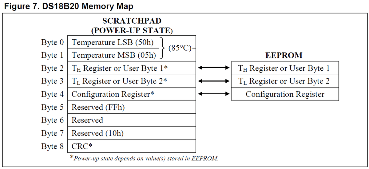
なおSCRATCHPADは下記を見るとレジスタ(記憶装置)で構成されたメモリ(RAMみたいな物??)みたいです。

なお分解能(9~12bit=0.0625~0.5℃)は上記Table2の通り"MAX CONVERSION TIME"で設定できます。今回は12bit(0.0625℃)に設定しました。

それでは分解能12bitで温度データを読み出してみました。
[IN]
from machine import Pin
import onewire, ds18x20, time

# 8-BIT FAMILY CODE  DS18S20 (10h) DS1822(22h) DS18B20 (28h)
ow = onewire.OneWire(Pin(12))   # GPIO 12 で OneWire バスを作成
ds = ds18x20.DS18X20(ow)        #ds18x20のClassからインスタンス

## rom code を取得
roms = ds.scan()        # 固有の64ビットroms <class 'list'>
rom=roms[0]             # 1-WireはDS18B20だけなので[0]

## temperature
ds.convert_temp()       # 温度データをSCRATCHPADに保存
time.sleep_ms(750)      # MAX CONVERSION TIMEの設定:750ms▶12bit=0.0625℃
temp=ds.read_temp(rom)  # 摂氏温度で取得
print(temp)
[OUT]
23.43756-2-4.SCRATCHPAD確認:read_scratch()
SCRATCHPADに書き込まれたデータをds18x20.read_scratch(rom)で確認しました。結果は下記の通りです。
データはBytearray型であり、計9Byteの情報を含む
各Byteに1Byteで情報を含む
[IN]
# SCRATCHPAD bytearray(9)を読出し
regi=ds.read_scratch(rom)
print(regi)
print(type(regi), len(regi))

for i in range(9): # SCRATCHPAD データの確認
    print(i,'%4d '%regi[i],hex(regi[i]))
[OUT]
bytearray(b'w\x010 \x7f\xff\t\x10\x82')
<class 'bytearray'> 9
0 119 0x77
1 1 0x1
2 48 0x30
3 32 0x20
4 127 0x7f
5 255 0xff
6 9 0x9
7 16 0x10
8 130 0x826-2-5.アラート設定の調整:write_scratch()
SCRATCHPADの中に下記3つの情報設定が可能です。
$${T_H}$$:高温時の警報(ALARM HIGH TRIGGER)
SCRATCHPADのByte2に1Byteの情報を含む
$${T_L}$$:低温時の警報(ALARM LOW TRIGGER)
SCRATCHPADのByte3に1Byteの情報を含む
$${EEPROM}$$:CONFIGURATION REGISTER
SCRATCHPADのByte4に1Byteの情報を含む


CONFIGURATION REGISTERはbit6(R1)とBit5(R0)の値($${0/1=2^2=4通り}$$)を設定することで分解能を設定できます。デフォルトは0x7f=01111111より、12bitで設定されています。

設定の変更はds18x20.write_scratch(rom, buf)を使用して3byteの情報をオブジェクトに渡すことで設定可能です。
参考として設定前後での結果を出力しました。設定後にSCRATCHPADのByte2~4の値が変更できることが確認できました。
※Byte4は設定値を同じにしているため実際の値に変更はありません。
[IN]
from machine import Pin
import onewire, ds18x20, time

# 8-BIT FAMILY CODE  DS18S20 (10h) DS1822(22h) DS18B20 (28h)
ow = onewire.OneWire(Pin(12))   # GPIO 12 で OneWire バスを作成
ds = ds18x20.DS18X20(ow)        #ds18x20のClassからインスタンス

## rom code を取得
roms = ds.scan()        # 固有の64ビットroms <class 'list'>
rom=roms[0]             # 1-WireはDS18B20だけなので[0]

## SCRATCHPAD bytearray(9)を読出し
regi=ds.read_scratch(rom)
print(f'{"#"*30}設定変更前{"#"*30}')
for i in range(9): # SCRATCHPAD データの確認
    print(i,'%4d '%regi[i],hex(regi[i]))

## SCRATCHPAD byte 2,3,4 TH,TL,Configurationを書換え
def set_config(rom:bytearray, th:int, tl:int, config:int):
    buf = bytearray(3)
    buf[0]=th  # TH Register:ALARM HIGH TRIGGER
    buf[1]=tl  # TL Register:ALARM LOW TRIGGER
    buf[2]=config  # Configuration Register
    ds.write_scratch(rom, buf)

#設定変更
set_config(rom=rom,
           th=0x50,  # TH Register:0x30=48℃
           tl=0x10,  # TL Register:0x20=32℃
           config=0x7f)  # Configuration Register:0x7f=01111111

## SCRATCHPAD bytearray(9)を読出して書込みデータを確認
regi=ds.read_scratch(rom)
# SCRATCHPAD data-list  データの確認
print(f'{"#"*30}設定変更後{"#"*30}')
for i in range(9): # SCRATCHPAD データの確認
print(i,'%4d '%regi[i],hex(regi[i]))[OUT]
##############################設定変更前##############################
0 129 0x81
1 1 0x1
2 48 0x30
3 32 0x20
4 127 0x7f
5 255 0xff
6 15 0xf
7 16 0x10
8 156 0x9c
##############################設定変更後##############################
0 129 0x81
1 1 0x1
2 80 0x50
3 16 0x10
4 127 0x7f
5 255 0xff
6 15 0xf
7 16 0x10
8 219 0xdb6-3.スクリプト実行
スクリプトを作成し、実行しました。
実行結果が見えるようにprint文で出力可視化しました。
[IN]
from machine import Pin
import onewire, ds18x20, time

# 8-BIT FAMILY CODE  DS18S20 (10h) DS1822(22h) DS18B20 (28h)
ow = onewire.OneWire(Pin(12))   # GPIO 12 で OneWire バスを作成
ds = ds18x20.DS18X20(ow)        #ds18x20のClassからインスタンス

## rom code を取得
roms = ds.scan()        # 固有の64ビットroms <class 'list'>
print('roms=',roms)
print(type(roms), len(roms))

rom=roms[0]             # 1-WireはDS18B20だけなので[0]
print(rom)
print([hex(i) for i in rom])
print(type(rom), len(rom))

## temperature
ds.convert_temp()       # 温度データをSCRATCHPADに保存
time.sleep_ms(750)      # MAX CONVERSION TIMEの設定:750ms▶12bit=0.0625℃
temp=ds.read_temp(rom)  # 摂氏温度で取得
print(f'温度:{temp}℃')

## SCRATCHPAD bytearray(9)を読出し
print(f'{"#"*30}設定変更前{"#"*30}')
regi=ds.read_scratch(rom)
print(regi)
print(type(regi), len(regi))

for i in range(9): # SCRATCHPAD データの確認
    print(i,'%4d '%regi[i],hex(regi[i]))

## SCRATCHPAD byte 2,3,4 TH,TL,Configurationを書換え
def set_config(rom:bytearray, th:int, tl:int, config:int):
    buf = bytearray(3)
    buf[0]=th  # TH Register:ALARM HIGH TRIGGER
    buf[1]=tl  # TL Register:ALARM LOW TRIGGER
    buf[2]=config  # Configuration Register
    ds.write_scratch(rom, buf)

#設定変更
set_config(rom=rom,
           th=0x50,  # TH Register:0x30=48℃
           tl=0x10,  # TL Register:0x20=32℃
           config=0x7f)  # Configuration Register:0x7f=01111111

## SCRATCHPAD bytearray(9)を読出して書込みデータを確認
print(f'{"#"*30}設定変更後{"#"*30}')
regi=ds.read_scratch(rom)
print(regi)
print(type(regi), len(regi))

# SCRATCHPAD data-list  データの確認
for i in range(9): # SCRATCHPAD データの確認
    print(i,'%4d '%regi[i],hex(regi[i]))
[OUT]
roms= [bytearray(b'(*\xf9\x8f\x0e\x00\x00\x85')]
<class 'list'> 1
bytearray(b'(*\xf9\x8f\x0e\x00\x00\x85')
['0x28', '0x2a', '0xf9', '0x8f', '0xe', '0x0', '0x0', '0x85']
<class 'bytearray'> 8
温度:23.9375℃
##############################設定変更前##############################
bytearray(b'\x83\x010 \x7f\xff\r\x10\x8b')
<class 'bytearray'> 9
0 131 0x83
1 1 0x1
2 48 0x30
3 32 0x20
4 127 0x7f
5 255 0xff
6 13 0xd
7 16 0x10
8 139 0x8b
##############################設定変更後##############################
bytearray(b'\x83\x01P\x10\x7f\xff\r\x10\xcc')
<class 'bytearray'> 9
0 131 0x83
1 1 0x1
2 80 0x50
3 16 0x10
4 127 0x7f
5 255 0xff
6 13 0xd
7 16 0x10
8 204 0xcc6-4.参考:ALARMの動作確認
ALARM設定温度($${T_H}$$、$${T_L}$$)を超過すると、ALARM SEARCHコマンドで状態を確認することが出来ます。

参考までにALARMが動作した時の挙動を確認しました。上限温度(TH)を30℃に設定し、指で温度を温めることで出力の変化を確認しました。
多分ALARM SEARCHコマンドが必要なのですが、SCRACHPADの情報(read_scratch(rom))からだけだと判断できませんでした。

[IN]
from machine import Pin
import onewire, ds18x20, time

# 8-BIT FAMILY CODE  DS18S20 (10h) DS1822(22h) DS18B20 (28h)
ow = onewire.OneWire(Pin(12))   # GPIO 12 で OneWire バスを作成
ds = ds18x20.DS18X20(ow)        #ds18x20のClassからインスタンス

## rom code を取得
roms = ds.scan()        # 固有の64ビットroms <class 'list'>
rom=roms[0]             # 1-WireはDS18B20だけなので[0]

## temperature
ds.convert_temp()       # 温度データをSCRATCHPADに保存
time.sleep_ms(750)      # MAX CONVERSION TIMEの設定:750ms▶12bit=0.0625℃
temp=ds.read_temp(rom)  # 摂氏温度で取得
print(f'温度:{temp}℃')

## SCRATCHPAD bytearray(9)を読出し
def set_config(rom:bytearray, th:int, tl:int, config:int):
    buf = bytearray(3)
    buf[0]=th  # TH Register:ALARM HIGH TRIGGER
    buf[1]=tl  # TL Register:ALARM LOW TRIGGER
    buf[2]=config  # Configuration Register
    ds.write_scratch(rom, buf)

#設定変更
set_config(rom=rom,
           th=30,  # TH Register
           tl=0,  # TL Register
           config=0x7f)  # Configuration Register:0x7f=01111111

## SCRATCHPAD bytearray(9)を読出して書込みデータを確認
regi=ds.read_scratch(rom)
print(regi)
# SCRATCHPAD data-list  データの確認
for i in range(9): # SCRATCHPAD データの確認
print(i,'%4d '%regi[i],hex(regi[i]))[OUT]
温度:23.8125℃
bytearray(b'}\x01\x1e\x00\x7f\xff\x03\x10\x94')
0 125 0x7d
1 1 0x1
2 30 0x1e
3 0 0x0
4 127 0x7f
5 255 0xff
6 3 0x3
7 16 0x10
8 148 0x94[OUT]
温度:30.4375℃
bytearray(b'\xe7\x01\x1e\x00\x7f\xff\t\x10\x19')
0 231 0xe7
1 1 0x1
2 30 0x1e
3 0 0x0
4 127 0x7f
5 255 0xff
6 9 0x9
7 16 0x10
8 25 0x197.Pythonスクリプト(Raspberry Pi)
Pythonでコード作成しました。コードは下記記事を参照しました。
7-1.任意:デバイス接続の確認
通信はないため、外観チェックだけしておきます。
参考までにPullup抵抗が機能しているか”raspi-gpio get”でGPIO4ピンのlevelがHigh(1)になっているか確認します。
[IN]
raspi-gpio get

[OUT]
-
7-2.コードの設計思想
設計思想は下記の通りです。
カーネルモジュールのロード:modprobe コマンドを実行
ちゃんと配線できていないと「modprobe: ERROR: could not insert 'w1_therm': Operation not permitted」発生
w1_slaveファイル抽出:"ls /sys/bus/w1/devices/"ディレクトリ内の28から始まるフォルダ内にあるw1_slaveファイルをglobで抽出
CMD実行:処理はPython標準ライブラリのOSとsubprocessで実行
温度計算:得られるデータは摂氏(℃)のため、華氏(℉)は手動で計算
7-2ー1.globでw1_slaveファイル抽出
globでw1_slaveファイルを抽出します。本ファイルは”ls /sys/bus/w1/devices/”コマンドで確認出来たファイルと同じになります。
[IN]
# -*- coding: utf-8 -*-
import os
import glob
import time
import subprocess

os.system('modprobe w1-gpio')
os.system('modprobe w1-therm')

base_dir = '/sys/bus/w1/devices/'
device_folder = glob.glob(base_dir + '28*')[0]
device_file = device_folder + '/w1_slave'
device_file[OUT]
'/sys/bus/w1/devices/28-00000e8ff92a/w1_slave'7-2ー2.生データ抽出
生データの取得関数の動作を確認しました。結果は下記の通り。
生データ(out)とエラー情報(err)はByte型で出力される
Byte.decodeで文字列に変換
データに改行の情報が含まれるため'\n'で分離
分離することでデータ数3のリストを取得
[IN]
def read_temp_raw(verbose=False):
    catdata = subprocess.Popen(['cat',device_file], #catコマンドでw1_slaveファイルを読み込む
                               stdout=subprocess.PIPE, #標準出力をパイプに接続
                               stderr=subprocess.PIPE) #標準エラー出力をパイプに接続
    out,err = catdata.communicate() #catコマンドの実行
    out_decode = out.decode('utf-8') #バイト列を文字列に変換
    if verbose:
        print(f'out: {out}, type: {type(out)}')
        print(f'err: {err}, type: {type(err)}')
        print(f'out_decode: {out_decode}, type: {type(out_decode)}')
        print(f'{"-"*60}')
    lines = out_decode.split('\n') #改行で分割
    return lines

lines = read_temp_raw(verbose=True)
print(lines)
print(f'Type: {type(lines)}, Len: {len(lines)}')
[OUT]
out: b'97 01 4b 46 7f ff 09 10 1c : crc=1c YES\n97 01 4b 46 7f ff 09 10 1c t=25437\n', type: <class 'bytes'>
err: b'', type: <class 'bytes'>
out_decode: 97 01 4b 46 7f ff 09 10 1c : crc=1c YES
97 01 4b 46 7f ff 09 10 1c t=25437
, type: <class 'str'>
------------------------------------------------------------
['97 01 4b 46 7f ff 09 10 1c : crc=1c YES', '97 01 4b 46 7f ff 09 10 1c t=25437', '']
Type: <class 'list'>, Len: 37-2ー3.実データの計算
得られた生データ(リストに変換済み)を下記の通り処理しました。
生データのList[0]の最後の3文字が"YES"で無ければ再読み込みする
"t="の後ろにデータ情報が含まれている
"t="の文字列の位置をfind()で確認
"t="除外のため、取得位置から2文字目以降のデータをスライスで抽出
温度データ[℃]の桁数を合わせるため1000で割る
得られた摂氏温度[℃]を華氏温度[℉]に変換(計算式を記載)
[IN]
lines = read_temp_raw(verbose=False)

def read_temp(verbose=False):
    lines = read_temp_raw()
    #読み込みエラーが発生した場合、再読み込み
    while lines[0].strip()[-3:] != 'YES':
        time.sleep(0.2)
        lines = read_temp_raw()

    equals_pos = lines[1].find('t=') #t=の位置を検索
    print(f'equals_pos: {equals_pos}')
    if equals_pos != -1:
        temp_string = lines[1][equals_pos+2:]
        temp_c = float(temp_string) / 1000.0 #摂氏温度に変換
        temp_f = temp_c * 9.0 / 5.0 + 32.0 #華氏温度に変換 F = C * 9/5 + 32
        if verbose:
            print(f'Raw_Data(All): {lines}, Len: {len(lines)}')
            print(f'Raw_Data(0): {lines[0]}, Type: {type(lines[0])}, Len: {len(lines[0])}')
            print(f'Raw_Data(1): {lines[1]}, Type: {type(lines[1])}, Len: {len(lines[1])}')
            print(f'temp_string: {temp_string}, type: {type(temp_string)}')
        return temp_c, temp_f


temp = read_temp(verbose=True)
print(temp)
[OUT]
equals_pos: 27
Raw_Data(All): ['9c 01 4b 46 7f ff 04 10 7a : crc=7a YES', '9c 01 4b 46 7f ff 04 10 7a t=25750', ''], Len: 3
Raw_Data(0): 9c 01 4b 46 7f ff 04 10 7a : crc=7a YES, Type: <class 'str'>, Len: 39
Raw_Data(1): 9c 01 4b 46 7f ff 04 10 7a t=25750, Type: <class 'str'>, Len: 34
temp_string: 25750, type: <class 'str'>
(25.75, 78.35)7-3.スクリプト実行
実行結果は下記の通りです。
GifはVerboseはFalseにして温度のみ表示しました。
[IN]
import os
import glob
import time
import subprocess

#デジタル温度センサ(1wire)DS18B20+
#カーネルモジュールのロード
os.system('modprobe w1-gpio')
os.system('modprobe w1-therm')

#w1_slaveファイルのパスを取得
base_dir = '/sys/bus/w1/devices/' #デバイスフォルダのパス
device_folder = glob.glob(base_dir + '28*')[0] #28-で始まるフォルダを取得
device_file = device_folder + '/w1_slave' #w1_slaveファイルのパス

def read_temp_raw(verbose=False):
    catdata = subprocess.Popen(['cat',device_file], #catコマンドでw1_slaveファイルを読み込む
                               stdout=subprocess.PIPE, #標準出力をパイプに接続
                               stderr=subprocess.PIPE) #標準エラー出力をパイプに接続
    out,err = catdata.communicate() #catコマンドの実行
    out_decode = out.decode('utf-8') #バイト列を文字列に変換
    if verbose:
        print(f'out: {out}, type: {type(out)}')
        print(f'err: {err}, type: {type(err)}')
        print(f'out_decode: {out_decode}, type: {type(out_decode)}')
        print(f'{"-"*60}')
    lines = out_decode.split('\n') #改行で分割
    return lines

def read_temp(verbose=False):
    lines = read_temp_raw(verbose=True)
    #読み込みエラーが発生した場合、再読み込み
    while lines[0].strip()[-3:] != 'YES':
        time.sleep(0.2)
        lines = read_temp_raw()

    equals_pos = lines[1].find('t=') #t=の位置を検索
    if equals_pos != -1:
        temp_string = lines[1][equals_pos+2:]
        temp_c = float(temp_string) / 1000.0 #摂氏温度に変換
        temp_f = temp_c * 9.0 / 5.0 + 32.0 #華氏温度に変換 F = C * 9/5 + 32
        if verbose:
            print(f'Raw_Data(All): {lines}, Len: {len(lines)}')
            print(f'Raw_Data(0): {lines[0]}, Type: {type(lines[0])}, Len: {len(lines[0])}')
            print(f'Raw_Data(1): {lines[1]}, Type: {type(lines[1])}, Len: {len(lines[1])}')
            print(f'temp_string: {temp_string}, type: {type(temp_string)}')
        return temp_c, temp_f

while True:
    s = "celsius: {0:.3f}, fahrenheit: {1:.3f}" #温度データの表示フォーマット:分解能が0.0625℃のため小数点以下3桁まで表示
    temp = read_temp(verbose=True) #(摂氏, 華氏)のタプルの温度データを取得
    print(s.format(*temp))
    print(f'{"#"*60}', end='\n\n')
    time.sleep(1)
[OUT]
out: b'9c 01 4b 46 7f ff 04 10 7a : crc=7a YES\n9c 01 4b 46 7f ff 04 10 7a t=25750\n', type: <class 'bytes'>
err: b'', type: <class 'bytes'>
out_decode: 9c 01 4b 46 7f ff 04 10 7a : crc=7a YES
9c 01 4b 46 7f ff 04 10 7a t=25750
, type: <class 'str'>
------------------------------------------------------------
Raw_Data(All): ['9c 01 4b 46 7f ff 04 10 7a : crc=7a YES', '9c 01 4b 46 7f ff 04 10 7a t=25750', ''], Len: 3
Raw_Data(0): 9c 01 4b 46 7f ff 04 10 7a : crc=7a YES, Type: <class 'str'>, Len: 39
Raw_Data(1): 9c 01 4b 46 7f ff 04 10 7a t=25750, Type: <class 'str'>, Len: 34
temp_string: 25750, type: <class 'str'>
celsius: 25.750, fahrenheit: 78.350
############################################################
8.所感
簡単な所感は下記の通り
1-Wireはほとんど使う機会なかったけど、Maxim社(現アナログ・デバイセズ社)の商標特許なのでSPI/I2C/UARTよりは学習の必要性は低いかも
1-Wireはほぼモジュールだよりで実装したため理解がまだまだ浅い。
ブロック図はダイオード(整流器)がついているので、変なところに電流は流れない気がするけど、なんで配線間違えて高温になったのかがわからん。
今更だけど860円って結構お高い!ADコンバータがあるなら「温度センサーIC MCP9700A-E/TO」あたりを使った方が(精度は±2℃のためよくないけど)、コスパは良いと思う。そもそもアナログ出力とデジタル出力のセンサを比較するのが無意味かもしれないけど。

参考資料
別添1 Python関係
別添2 技術関係
あとがき
センサーで火傷しそうになって焦った。とりあえず、機器が安定するまではそばにいた方が良いことは理解できた。