NINA-B302(nRF52840)のTIMERを使いたい(2)

こつこつと、NINA-B302(nRF52840)をいじっていきたいと思います。環境の立ち上げは↓を見てください。zephyrになってTIMERの割り込みの使用方法がわからないです。効率的に使うにはPPIというのを使うらしいので、sampleプログラムを動かしました。それだけ。
nrfxのサンプルを使用します。どこにあるか分かりにくい、ので下記に示します。
C:\Users\<USER>\ncs\v1.6.1\zephyr\samples\boards\nrf\nrfx
読み込み設定は下記。

下記が main.cです。そのままですが載せておきます。
#define INPUT_PIN DT_GPIO_PIN(DT_ALIAS(sw1), gpios)
#define OUTPUT_PIN DT_GPIO_PIN(DT_ALIAS(led0), gpios)
は、変えたかな。
ボード的には、SW2を押すと、赤LEDがトグルします。
/*
* Copyright (c) 2019 Nordic Semiconductor ASA
*
* SPDX-License-Identifier: Apache-2.0
*/
#include <zephyr.h>
#include <nrfx_gpiote.h>
#include <helpers/nrfx_gppi.h>
#if defined(DPPI_PRESENT)
#include <nrfx_dppi.h>
#else
#include <nrfx_ppi.h>
#endif
// #include <nrf_drv_timer.h>
#include <logging/log.h>
LOG_MODULE_REGISTER(nrfx_sample, LOG_LEVEL_INF);
#define INPUT_PIN DT_GPIO_PIN(DT_ALIAS(sw1), gpios)
#define OUTPUT_PIN DT_GPIO_PIN(DT_ALIAS(led0), gpios)
static void button_handler(nrfx_gpiote_pin_t pin, nrf_gpiote_polarity_t action)
{
LOG_INF("GPIO input event callback");
}
void main(void)
{
LOG_INF("nrfx_gpiote sample on %s", CONFIG_BOARD);
nrfx_err_t err;
/* Connect GPIOTE_0 IRQ to nrfx_gpiote_irq_handler */
IRQ_CONNECT(DT_IRQN(DT_NODELABEL(gpiote)),
DT_IRQ(DT_NODELABEL(gpiote), priority),
nrfx_isr, nrfx_gpiote_irq_handler, 0);
/* Initialize GPIOTE (the interrupt priority passed as the parameter
* here is ignored, see nrfx_glue.h).
*/
err = nrfx_gpiote_init(0);
if (err != NRFX_SUCCESS) {
LOG_ERR("nrfx_gpiote_init error: %08x", err);
return;
}
nrfx_gpiote_in_config_t const in_config = {
.sense = NRF_GPIOTE_POLARITY_HITOLO,
.pull = NRF_GPIO_PIN_PULLUP,
.is_watcher = false,
.hi_accuracy = true,
.skip_gpio_setup = false,
};
/* Initialize input pin to generate event on high to low transition
* (falling edge) and call button_handler()
*/
err = nrfx_gpiote_in_init(INPUT_PIN, &in_config, button_handler);
if (err != NRFX_SUCCESS) {
LOG_ERR("nrfx_gpiote_in_init error: %08x", err);
return;
}
nrfx_gpiote_out_config_t const out_config = {
.action = NRF_GPIOTE_POLARITY_TOGGLE,
.init_state = 1,
.task_pin = true,
};
/* Initialize output pin. SET task will turn the LED on,
* CLR will turn it off and OUT will toggle it.
*/
err = nrfx_gpiote_out_init(OUTPUT_PIN, &out_config);
if (err != NRFX_SUCCESS) {
LOG_ERR("nrfx_gpiote_out_init error: %08x", err);
return;
}
nrfx_gpiote_in_event_enable(INPUT_PIN, true);
nrfx_gpiote_out_task_enable(OUTPUT_PIN);
LOG_INF("nrfx_gpiote initialized");
/* Allocate a (D)PPI channel. */
#if defined(DPPI_PRESENT)
uint8_t channel;
err = nrfx_dppi_channel_alloc(&channel);
#else
nrf_ppi_channel_t channel;
err = nrfx_ppi_channel_alloc(&channel);
#endif
if (err != NRFX_SUCCESS) {
LOG_ERR("(D)PPI channel allocation error: %08x", err);
return;
}
/* Configure endpoints of the channel so that the input pin event is
* connected with the output pin OUT task. This means that each time
* the button is pressed, the LED pin will be toggled.
*/
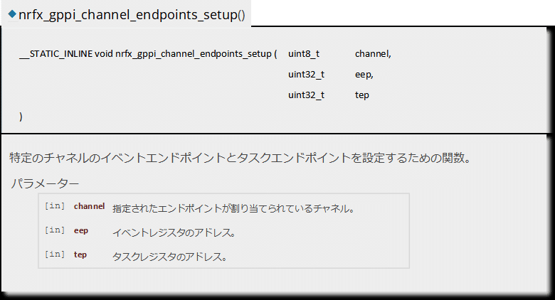
nrfx_gppi_channel_endpoints_setup(channel,
nrf_gpiote_event_address_get(NRF_GPIOTE,
nrfx_gpiote_in_event_get(INPUT_PIN)),
nrf_gpiote_task_address_get(NRF_GPIOTE,
nrfx_gpiote_in_event_get(OUTPUT_PIN)));
/* Enable (D)PPI channel. */
#if defined(DPPI_PRESENT)
err = nrfx_dppi_channel_enable(channel);
#else
err = nrfx_ppi_channel_enable(channel);
#endif
if (err != NRFX_SUCCESS) {
LOG_ERR("Failed to enable (D)PPI channel, error: %08x", err);
return;
}
LOG_INF("(D)PPI configured, leaving main()");
}nrfx_gpiote_in_config_t 構造体リファレンス(元ネタ)

nrfx_gpiote_in_init()関数(元ネタ)

nrfx_gppi_channel_endpoint_setup()関数(元ネタ)
nrf_gpiote_event_address_get()関数(元ネタ)

その他の定義など。
nrf52840.hで下記の設定がされてます。
nrf52840.h
#define NRF_GPIOTE                  ((NRF_GPIOTE_Type*)        NRF_GPIOTE_BASE)
#define NRF_GPIOTE_BASE             0x40006000UL
/**
 * @brief GPIO Tasks and Events (GPIOTE)
 */
typedef struct {                                /*!< (@ 0x40006000) GPIOTE Structure                                           */
 __OM  uint32_t  TASKS_OUT[8];                 /*!< (@ 0x00000000) Description collection: Task for writing to pin
                                                                   specified in CONFIG[n].PSEL. Action on pin
                                                                   is configured in CONFIG[n].POLARITY.                       */
 __IM  uint32_t  RESERVED[4];
 __OM  uint32_t  TASKS_SET[8];                 /*!< (@ 0x00000030) Description collection: Task for writing to pin
                                                                   specified in CONFIG[n].PSEL. Action on pin
                                                                   is to set it high.                                         */
 __IM  uint32_t  RESERVED1[4];
 __OM  uint32_t  TASKS_CLR[8];                 /*!< (@ 0x00000060) Description collection: Task for writing to pin
                                                                   specified in CONFIG[n].PSEL. Action on pin
                                                                   is to set it low.                                          */
 __IM  uint32_t  RESERVED2[32];
 __IOM uint32_t  EVENTS_IN[8];                 /*!< (@ 0x00000100) Description collection: Event generated from
                                                                   pin specified in CONFIG[n].PSEL                            */
 __IM  uint32_t  RESERVED3[23];
 __IOM uint32_t  EVENTS_PORT;                  /*!< (@ 0x0000017C) Event generated from multiple input GPIO pins
                                                                   with SENSE mechanism enabled                               */
 __IM  uint32_t  RESERVED4[97];
 __IOM uint32_t  INTENSET;                     /*!< (@ 0x00000304) Enable interrupt                                           */
 __IOM uint32_t  INTENCLR;                     /*!< (@ 0x00000308) Disable interrupt                                          */
 __IM  uint32_t  RESERVED5[129];
 __IOM uint32_t  CONFIG[8];                    /*!< (@ 0x00000510) Description collection: Configuration for OUT[n],
                                                                   SET[n], and CLR[n] tasks and IN[n] event                   */
} NRF_GPIOTE_Type;                              /*!< Size = 1328 (0x530)                                                       */