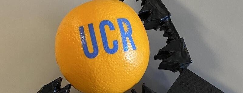
空気圧式ソフトロボットの動きを制御するコンピュータメモリ。
空気圧式ソフトロボットは、加圧された空気でゴムのような柔らかい手足やグリッパーを動かす。
米国のNSF(National Science Foundation/全米科学財団/国立科学財団)は2021年08月04日に、カリフォルニア大学リバーサイド校のエンジニア(Engineers at University of California, Riverside)は、ソフトロボットの制御に使用できる空気動力のコンピュータメモリを発表したと報告した。
https://time-az.com/main/detail/74947
この技術革新は、ソフトロボットの発展を妨げる最大の要因の一つである、空気圧と電子機器の根本的な不一致を克服するものである。
この研究は、NSFからの資金提供を受け、PLOS Oneに掲載された。

空気圧式ソフトロボットは、加圧された空気を利用して、ゴムのような柔らかい手足やグリッパーを動かすもので、従来の剛性の高いロボットよりも繊細な作業を行うのに優れている。
また、人間にとってもより安全です。2014年に公開されたアニメ映画『Big Hero 6』に登場するヘルスケア・コンパニオン・ロボット「ベイマックス(Baymax)」が空圧式ロボットであるのには理由がある。

ソフトロボティクスを進化させるために、生物工学者のシェーン・ホアン(Shane Hoang)とウィリアム・グローバー(William Grover)、コンピュータ科学者のフィリップ・ブリスク(Philip Brisk)、機械工学者のコンスタンティノス・カリディス(Konstantinos Karydis)が率いるチームは、過去の事例を調べた。
「空圧論理とは、電子計算機よりも古く、サーモスタットなどの空調システムからピアノまで、高度な制御を可能にしていた。空気の論理とは、電気ではなく空気を回路や水路に流し、その圧力でオン/オフや真偽を表現するものである。現代のコンピューターでは、これらの論理状態を1と0のコードで表し、電荷を引き起こしたり、終わらせたりする。
空気圧式ソフトロボットには、可動部の位置を記憶・保持する方法が必要で、研究者たちは、ソフトロボットのための空気圧式論理「メモリ」を作ることができれば、現在その目的のために使われている電子メモリをなくすことができると考えた。
研究者たちは、電子トランジスターの代わりにマイクロ流体バルブを使って、空気圧式RAM(Random-Access Memory/ランダムアクセスメモリー)チップを作った。このマイクロ流体バルブは、本来、マイクロ流体チップ上の液体の流れを制御するために設計されたものであるがが、空気の流れも制御することができる。
このバルブは、空気の供給ラインから切り離されても、圧力差に対して密閉された状態を維持し、閉じ込められた圧力差がメモリとして機能し、ロボットのアクチュエーターの状態を維持する。このバルブを高密度に配列することで、高度な操作が可能となり、空気圧式ロボットの制御に一般的に使用されている高価でかさばる電力消費型の電子機器を削減することができる。
そういえば、昔、空気ではなく、水の流れてコンピュータができると話したことがあった。
ただ嵩張った。

Fig 1.
Conventional methods for controlling pneumatic soft robots require a dedicated electronic control line and solenoid valve for each independent actuator (left). Using our pneumatic random access memory (RAM), the same amount of electromechanical control hardware can operate many more actuators while still providing independent control of each actuator (right).
https://doi.org/10.1371/journal.pone.0254524.g001

Table 1. Comparisons between soft lithography valves (used in most previous work on microfabricated pneumatic logic control of soft robots) and monolithic membrane valves (adapted for use in this work).
https://doi.org/10.1371/journal.pone.0254524.t001

Fig 2. Adapting normally-closed monolithic membrane valves for soft robotic applications.
(A) In conventional microfluidic monolithic membrane valves [26], fluid flow between the Input channel and the Output channel is blocked by a flexible silicone membrane (blue). When a vacuum is applied to the Control channel, the silicone membrane is pulled into the Control chamber, opening a path for flow between the Input and Output channels (green dashed arrow). Though adequate for microfluidic applications, the rate of air flow through conventional monolithic membrane valves is too small for controlling larger and faster-moving soft robots. (B) Increasing the widths of the Input and Output channels significantly increases the rate of flow through the valve, but this change brings an undesirable side effect: the silicone membrane can stretch into the Input and Output channels as if they were Control chambers, creating unintentional flow paths (red dashed arrows). (C) Using multiple narrow-width Input and Output channels in parallel eliminates the risk of unintentional flow paths while still maintaining a high flow rate suitable for use controlling soft robotic actuators.
https://doi.org/10.1371/journal.pone.0254524.g002

Fig 3. A “truth table” showing cross-sections of a high-flow monolithic membrane valve during each of the eight possible combinations of atmospheric pressure (A) and vacuum (V) applied to the valve’s three connections (Input, Control, and Output).
When atmospheric pressure is applied to all three connections on a valve, the valve has equal pressure applied on both sides of the flexible membrane, so the membrane remains in its resting (closed) state (AAA). If the Control connection on a valve receives atmospheric pressure, then the valve will remain closed, regardless of whether the Input and Output connections receive vacuum or pressure (AAV, VAA, and VAV). When vacuum is applied to all three connections on a valve, the valve has the same pressure on both sides of the flexible membrane, so the membrane remains at rest and the valve stays closed (VVV). If vacuum is applied to the Control connection while the Input and Output connections are at atmospheric pressure, then the pressure differential across the flexible membrane causes the membrane to stretch into the Control chamber and opens the valve (AVA). When vacuum is applied to the Control connection and the Output connection while the Input connection is at atmospheric pressure (AVV), the valve opens and air flows from the Input to the Output. Likewise, when vacuum is applied to the Control and Input connections while the Output is at atmospheric pressure (VVA), the valve opens and air flows from the Output to the Input. In both cases, the valve remains open and air continues to flow as long as there is a pressure difference between the Input and Output connections. However, if the pressures at the Input and Output connections equalize (both become vacuum, or both become atmospheric pressure), the valve will automatically transition to a new state. If both the Input and the Output reach atmospheric pressure, then the valve will transition to state AVA and remain open. But if both the Input and the Output reach vacuum, then the valve will transition to state VVV and automatically close. This automatic transition from state AVV or VVA to state VVV is particularly useful because it can “trap” a vacuum in a region of a pneumatic logic circuit; the vacuum remains trapped until it is vented by opening a path to atmospheric pressure using state AVV or VVA again. This serves as a one-bit nonvolatile pneumatic “memory”: a section of channel represents 1 (TRUE) if it contains a trapped vacuum and 0 (FALSE) if it contains atmospheric-pressure air.
https://doi.org/10.1371/journal.pone.0254524.g003

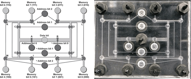
Fig 4. Logic diagram for our pneumatic eight-bit random-access memory.
Four solenoid valves (orange region in the diagram) provide three pneumatic Address bits (for selecting which Memory bit to set) and one Data bit (for setting the value of the selected Memory bit); the rest of the logic diagram (blue region) is performed by a pneumatic logic circuit. Eight outputs (labeled Memory bits 0 through 7) provide access to the eight stored pressure levels in the pneumatic RAM and are connected to eight fingers in two soft robotic hands.
https://doi.org/10.1371/journal.pone.0254524.g004

Fig 5. Design and photograph of a pneumatic eight-bit RAM for controlling soft robotic fingers.
The 6.35 cm × 5.08 cm chip includes eight ports for connecting fingers to the Memory bits, a single Data bit connection that sets the state (contracted or extended) of each finger, three Address bit connections (and their negations, marked with “¬”) which are used to select which Memory bit (and therefore which finger) to set, and 14 pneumatic valves (labeled A through N) that execute the logical functions shown in the blue box in Fig 4.
https://doi.org/10.1371/journal.pone.0254524.g005

Fig 6. Pressure inside each channel (either green for vacuum, or red for atmospheric pressure) while using the pneumatic eight-bit RAM to contract and extend several soft robotic fingers.
In each step, the vacuum or pressure applied to the Address bits (AB0, AB1, AB2, and their negations ¬AB0, ¬AB1, ¬AB2) determine the route (highlighted in yellow) followed by the Data bit (DB) signal to the selected finger. Channels containing trapped vacuum “memories” are marked using a dotted line, and the binary representation of the contents of the pneumatic RAM is shown. A detailed explanation of each step is provided in the text, and a table showing the state of each valve (A through N) during each step and a video recording of the chip during operation are available as online Supplementary Information.
https://doi.org/10.1371/journal.pone.0254524.g006

Fig 7. Video frames from using the pneumatic eight-bit RAM to contract eight soft robotic fingers one-at-a-time.
The pneumatic RAM cycles through all eight addresses from 0002 to 1112 to set the pneumatic RAM’s memory to the values shown (from 0000 00012 to contract just Finger 0, to 1000 00002 to contract just Finger 7).
https://doi.org/10.1371/journal.pone.0254524.g007

Fig 8. Video frames from using the pneumatic RAM to set eight soft robotic fingers to all 256 different possible patterns, ranging from all extended (corresponding to a value of 0000 00002 or 0 stored in the pneumatic RAM) to all contracted (a value of 1111 11112 or 255 stored in the pneumatic RAM), with closeups of the fingers while the pneumatic RAM is storing the values 43, 85, 173, and 253.
Closeups of all 256 frames are available as Supplementary Information.
https://doi.org/10.1371/journal.pone.0254524.g008

Fig 9. Measuring the amount of time that the pneumatic RAM can “remember” the value of a Memory bit (and how long a soft robotic finger connected to the Memory bit can maintain its actuation state).
(A) At atmospheric pressure, the finger has a natural curve with an angle θ0. (B) At time = 0, the pneumatic RAM applies vacuum from the Data input to the Memory bit and the finger for an excessively-long 60 s, which causes the finger to contract an additional Δθ degrees. After 60 s the pneumatic RAM disconnects the Data vacuum from the Memory bit, but the finger remains contracted due to the vacuum trapped in the Memory bit and inside the finger. For the next hour, the pneumatic RAM cycled through three other fingers, contracting and extending one every ten seconds. Even though the pneumatic RAM chip’s operation introduces small amounts of atmospheric-pressure air to the first finger, the finger nonetheless remained 90% contracted 1 h after the applied vacuum was removed. Therefore, a trapped vacuum at a pneumatic RAM Memory bit can hold a finger contracted for at least an hour before needing to be “refreshed” by the pneumatic RAM. A closeup view of the first few seconds of this plot is available as online Supplementary Information.
https://doi.org/10.1371/journal.pone.0254524.g009

Fig 10. Video frames from using the pneumatic RAM and principles of time-division multiplexing (TDM) to control soft robotic fingers simultaneously playing the notes G, B, and D (a G-major chord) on an electric piano keyboard.
The plot shows the observed delay between the start of the first note of the chord and the last note of the chord, as a function of the cycle speed of the pneumatic RAM. At cycle frequencies above 5.56 Hz the pneumatic RAM’s performance degrades and the chord’s notes do not sound simultaneously, but below 5.56 Hz the notes sound within 1 to 2 seconds of each other.
https://doi.org/10.1371/journal.pone.0254524.g010

Fig 11. Video frame from using an eight-bit pneumatic RAM to control soft robotic fingers playing the music score shown on the right.
The music consists of “Mary Had a Little Lamb” (measures 1 through 8; demonstrating playing one note at a time with varying durations) followed by an arpeggiated G-major chord (measure 9; demonstrating playing and holding multiple notes simultaneously). Source video available as online Supplementary Information.
https://doi.org/10.1371/journal.pone.0254524.g011
Discussion
